Microchip Harmony PIC32 Bootloader
We were recently tasked with developing a new boot loader system on a Microchip PIC32MZ device. While Microchip offer useful bootloader functionality and libraries for use with the platform, we still contended with an older third-party closed source bootloader that had been used up to this point. We thought we’d share our experience with you here and talk about how we replaced the old bootloader over ethernet, without a programmer.
Device Properties
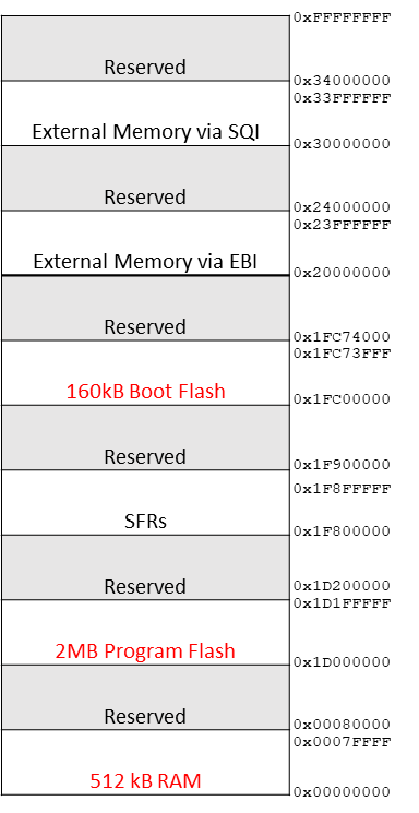
The PIC32MZ chosen was the 2048EFM144 model, which has 2MB of program flash, 512KB of RAM and 160KB of boot flash. One nice feature of this chip is we can split the Program flash into two banks, and decide which bank runs at startup with the help of the Harmony framework. MPLAB Harmony is an embedded software development framework that provides useful functionality (implemented as state machines) for embedded development, from peripheral drivers to network protocol stacks. With this we can potentially store two applications on the device, and switch between them as needed. Of course, in this case, each program file will be limited to just under 1MB in size.
Harmony Bootloader
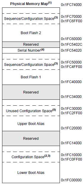
The Harmony bootloader is designed to be installed into boot flash memory seen below. Here we can see the boot flash consists of 2 banks – boot flash 1 and boot flash 2. Each boot flash bank is approximately 81,664 bytes. Boot flash is fragmented with critical device registers interspersed. We only program these configuration values once with the programmer. They should not be overwritten by subsequent firmware updates to avoid stability issues. It should be possible to use both banks of boot flash in a way similar to how we intend on using our program flash – keeping our bootloader under the size limitation of a single boot flash bank, and alternating the bank read based on subsequent bootloader updates. We found this to be too stringent in our case, and instead favored an approach where both boot flash banks were bridged using a simple fill in the linker script to make them appear contiguous to our compiler.
The bootloader code required some tweaking to get working the way we needed. With these edits complete, the code size is approximately 114,728 bytes, using O1 optimization. The large size is mostly due to our reliance on the TCP stack to support incoming UDP packets, which is our preferred way of receiving a firmware update.
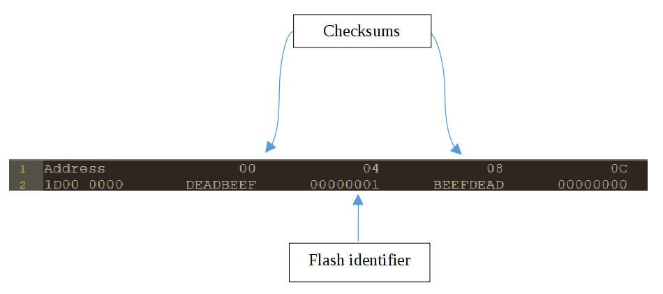
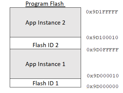
In addition to memory in boot flash, our bootloader also requires 32 bytes of program memory – 16 bytes per application image to maintain versioning and a checksum. After all, when the system is powered on, it is the bootloader that will look at both program flash banks, and decide which program bank contains the latest version of our application, and if the application is corrupted in any way. Thus, the largest any one application can grow to is just under 1MB. The first application instance can run from 0x1D00_0010 to 0x1D0F_FFFF, while the second application instance can run from 0x1D10_0010 to 0x1D1F_FFFF. A snapshot of the first 16 bytes in program memory can be seen below for version 1 of the application.
The framework makes it possible to do a ‘live update’ of a new firmware image onto the device, i.e. download and flash a firmware update while the existing firmware runs normally. Once the new image has been written down successfully, the version value is incremented, and the device is power cycled. The bootloader will load the image with the latest versioning, whose checksum is valid.
This bootloader project is intended to be the first image flashed to the device – using a programmer. In this sense, it determines the values for device configuration, and these values are initialized in system_init.c. When flashing subsequent images, we want to avoid overwriting these configuration values, as this can cause the device to behave in an unstable manner.
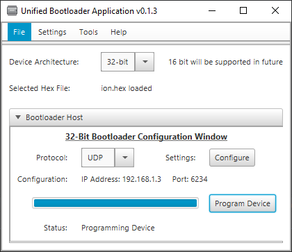
With the bootloader running, the device listens for the first application over ethernet, from either Microchip’s Unified Bootloader shown here, or from a custom desktop application. When this arrives, it is written to the device’s lower bank of program memory. At this point, when the device is power cycled, the bootloader runs and quickly decides it should handover to the application in program memory. With the bootloader no longer running, listening for firmware updates, this raises the question as to how we should enter bootloader mode again.
In our case, we worked around this by encapsulating bootloader functionality into our running application. Our running application listens out for a firmware update as a background task while still carrying out its primary function. Microchip call this feature ‘live update’. When a new firmware update is issued over ethernet, the first instance of the application running in program memory detects this update and writes the new application to the upper bank of program memory, before power cycling. The bootloader runs and selects the latest application from the upper bank. Should the checksum have failed in some way, the bootloader would have reverted to loading the application in the lower bank. This cycle can be repeated as many times as there are firmware updates. This is the normal behavior of our application.
Trampoline App
We had an added complication to this flow in our case. An existing generic third-party closed source firmware had already been flashed to the upper program flash memory bank to take on the role of a bootloader. Our customer had licensed this software, and had pre-existing devices in the field they wished to be able to upgrade – but did not have source code access for this boot loader.
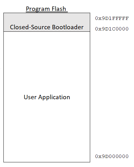
This boot loader firmware didn’t utilize program memory partitioning, so only a single application instance was supported in program memory at any given time, although this could be up to 1792KB in size. These had already been applied at factory. While the firmware was proprietary, with no source code available, we could see from memory dumps that it occupied approximately 256KB of program memory, beginning at address 0x9D1C_0000.
It seemed rather inefficient to not utilize our Microchip based bootloader in place of this bootloader. After all, we had the source code available to us for our new bootloader, and it fits well in boot flash memory. We tried to use our third-party closed source bootloader to flash the new bootloader to boot flash, but this caused the device to become unresponsive, a possible indication that device configuration values were overwritten. A list of these configuration values is shown below. So it wasn’t possible to use the closed-source bootloader to write to boot flash, but it could be used to program an application to program flash successfully. We came up with a plan to replace the closed source bootloader without the need for a device programmer. We created a modified Microchip bootloader which could be programmed over ethernet in the lower program memory bank. We called this application our trampoline app.
Our trampoline application was specially written so it could overwrite the boot flash safely. It does so by first unlocking the boot flash, then writing to only those pages in boot flash which do not hold device configuration values. It should be noted that this approach means subsequent application updates should use the same device configuration values. We did take a look at overwriting these device configuration values too but found the device can become unstable when re-programmed in the field.
| Register | Parameter | Code Description |
|---|---|---|
| DEVCFG0 | DEBUG | Background Debugger Enable |
| JTAGEN | JTAG Enable | |
| ICESEL | ICE/ICD Comm Channel Select | |
| TRCEN | Trace Enable | |
| BOOTISA | Boot ISA Selection | |
| FECCCON | Dynamic Flash ECC Configuration | |
| FSLEEP | Flash Sleep Mode | |
| DBGPER | Debug Mode CPU Access Permission | |
| SMCLR | Soft Master Clear Enable bit | |
| SOSCGAIN | Secondary Oscillator Gain Control bits | |
| SOSCBOOST | Secondary Oscillator Boost Kick Start Enable bit | |
| POSCGAIN | Primary Oscillator Gain Control bits | |
| POSCBOOST | Primary Oscillator Boost Kick Start Enable bit | |
| EJTAGBEN | EJTAG Boot | |
| CP | Code Protect | |
| DEVCFG1 | FNOSC | Oscillator Selection Bits |
| DMTINTV | DMT Count Window Interval | |
| FSOSCEN | Secondary Oscillator Enable | |
| IESO | Internal/External Switch Over | |
| POSCMOD | Primary Oscillator Configuration | |
| OSCIOFNC | CLKO Output Signal Active on the OSCO Pin | |
| FCKSM | Clock Switching and Monitor Selection | |
| WDTPS | Watchdog Timer Postscaler | |
| WDTSPGM | Watchdog Timer Stop During Flash Programming | |
| FWDTEN | Watchdog Timer Enable | |
| WINDIS | Watchdog Timer Window Mode | |
| FWDTWINSZ | Watchdog Timer Window Size | |
| DMTCNT | Deadman Timer Count Selection | |
| FDMTEN | Deadman Timer Enable | |
| DEVCFG2 | FPLLIDIV | System PLL Input Divider |
| FPLLRNG | System PLL Input Range | |
| FPLLICLK | System PLL Input Clock Selection | |
| FPLLMULT | System PLL Multiplier | |
| FPLLODIV | System PLL Output Clock Divider | |
| UPLLFSEL | USB PLL Input Frequency Selection | |
| DEVCFG3 | USERID | User ID |
| FMIIEN | Ethernet RMII/MII Enable | |
| FETHIO | Ethernet I/O Pin Select | |
| PGL1WAY | Permission Group Lock One Way Configuration | |
| PMDL1WAY | Peripheral Module Disable Configuration | |
| IOL1WAY | Peripheral Pin Select Configuration | |
| FUSBIDIO | USB USBID Selection | |
| BF1SEQ0 | TSEQ | Boot Flash True Sequence Number |
| CSEQ | Boot Flash Complement Sequence Number |
By using the existing closed source bootloader, we flashed our custom-built trampoline application to the lower bank over ethernet. We then used our trampoline application to flash our Microchip based bootloader. From this point on, the standard flow applied – the bootloader could be used to flash an image to the lower bank of program memory, and this application could be used to flash an image to the upper bank – overwriting the closed-source bootloader we wished to replace in the process. This cycle can repeat as many times as there are firmware updates.